Rereading my thesis shader: six techniques and a half vector that wasn't
My 2022 bachelor thesis was a GLSL material shader written by hand and measured against the physically based one in Three.js. It runs on this site now, so here is what's inside it: displacement, normal maps, roughness-blurred reflections, a Fresnel term, and the one-line bug behind most of the gap.
The Render Catalogue on this site is my bachelor thesis from 2022, up and running. The written half, Internetowe portfolio z renderowanymi grafikami 3D ("An online portfolio with rendered 3D graphics", Collegium Da Vinci, Poznań), runs to ninety pages in Polish. Most of them cover a Node server, a MongoDB collection and UML diagrams. The part worth reading is about twenty pages in the middle: a material shader written from scratch in GLSL, compared side by side with the MeshStandardMaterial that ships with Three.js.
This post is those twenty pages in English, with hindsight added. The viewer has a Shading toggle that switches between my shader and the Three.js one, so you can check everything below against the real thing.
The brief
I had four tiling materials authored in Substance Designer, each with six maps: base colour, normal, roughness, metallic, ambient occlusion and height. The job was one shader that made them look as close as possible to the physically based material in Three.js. The techniques on the list were diffuse and specular lighting, vertex displacement, normal mapping, a Fresnel term and environment reflections.
I chose deliberately not to write PBR. The Three.js standard material follows the physically based convention that games settled on, with a microfacet BRDF, energy conservation and metalness. My shader follows the older diffuse-plus-specular split of the Phong family instead. It computes the two terms separately, adds them together, and borrows a few PBR tricks to close the gap. What interested me was how close that could get.
Six maps go in, but the shader reads only five. It leaves out the metallic map on purpose. A real surface is either a metal or a dielectric (a non-metal), with nothing in between, so a map that fades smoothly from one to the other doesn't describe anything physical. And none of the four materials is a metal, so the answer for all of them is the same: dielectric.
Displacement, and the neighbour problem
The vertex shader pushes every vertex out along its normal by the height map:
vec3 height = texture2D(u_heightmap, vUv).r * normal * u_heightScale;
That moves the surface but leaves the normals alone. Each vertex still carries the normal of the undisplaced sphere, so a tile edge that now faces sideways is lit as if it still faced outwards. It gets worse: vertices that used to be hidden can come into view with normals pointing away from the camera.
The textbook fix is to recompute the normal from the displaced neighbours, and a vertex shader can't see its neighbours. Every invocation runs in isolation, which is the whole reason GPUs are fast. What a vertex can do is read the height map at any UV it likes. So it samples four points around itself (left, right, up and down), builds four edge vectors from the tangent, the bitangent and the height differences, and crosses each adjacent pair:
vec3 topRight    = cross(right, top);
vec3 topLeft     = cross(top, left);
vec3 bottomLeft  = cross(left, bottom);
vec3 bottomRight = cross(bottom, right);
vec3 heightNormal = normalize(topRight + topLeft + bottomLeft + bottomRight);
Each cross product estimates the normal of the displaced surface, and the average of four estimates is a better one. The next step is the one I'm still fondest of. With little or no displacement, the estimate is mostly noise. So the shader blends between the original normal and the rebuilt one in proportion to how far the surface actually moved:
vNormal = heightNormal * u_heightScale * 10.0 + vNormal * (1.0 - u_heightScale * 10.0);
The height scale tops out at 0.1, so the blend weight runs from exactly 0 to 1.
This costs two things. First, displacing per vertex needs a lot of vertices, so the original sphere had a million of them. The port here uses 66 thousand, which is still more than the detail needs at this size. Second, the displacement happens only in the vertex shader of the pass you can see. Shadows come from a separate pass that knows nothing about it, so the displaced sphere casts the shadow of a smooth one:
| Thesis shader | Three.js PBR |
|---|---|
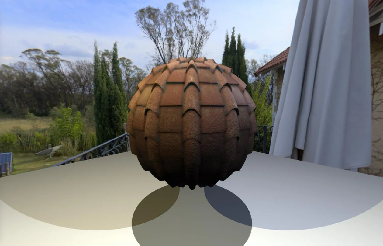 | 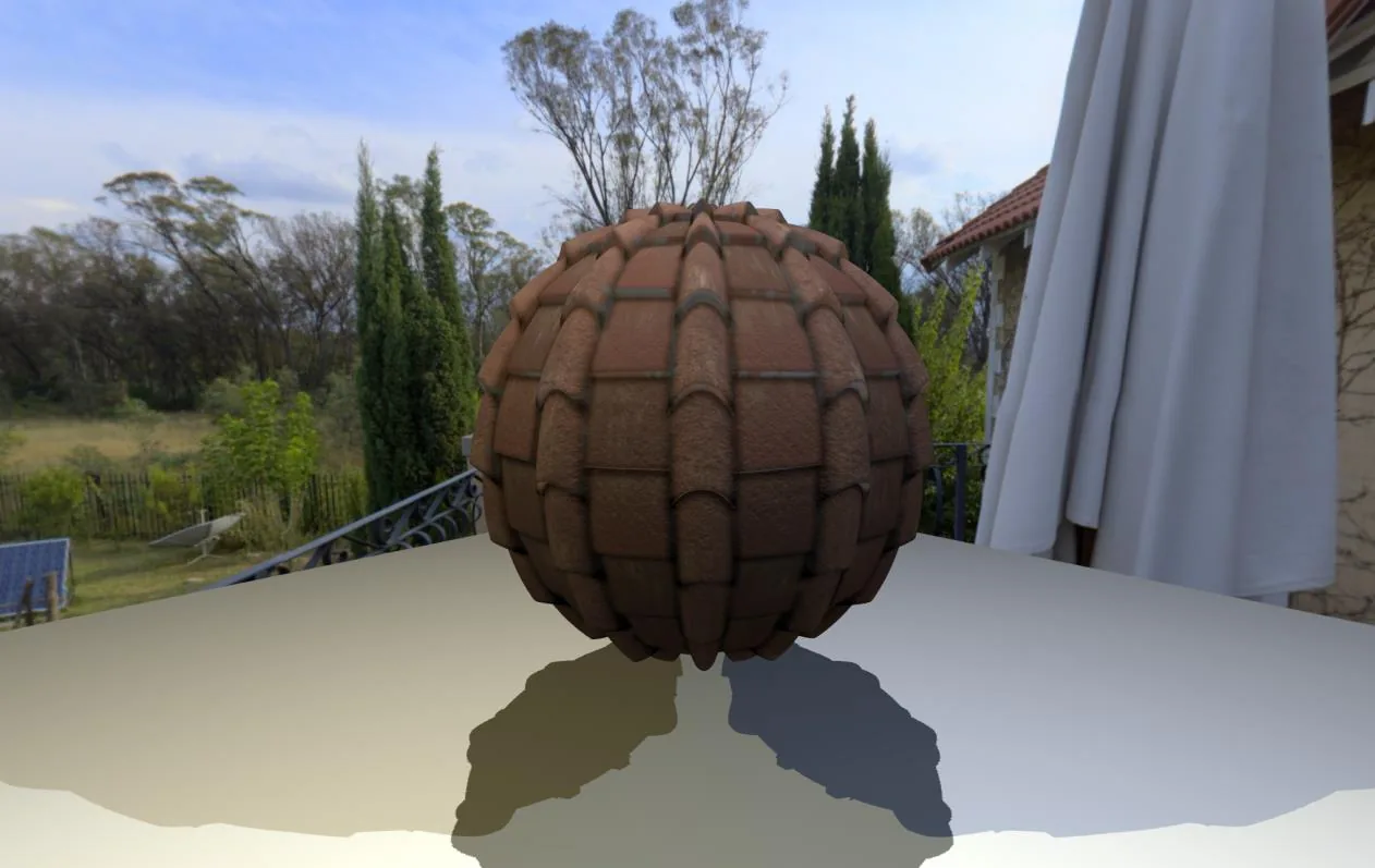 |
Look at the ground. The Three.js material applies its displacement map in the shadow pass as well, so its shadows follow the tile profile. Mine are perfect circles. The fix is a customDistanceMaterial that runs the same displacement (point lights render their shadows as distance, not depth). The thesis listed this among its simplifications, and it's the first difference you notice.
Normal maps: three small corrections
Per-pixel detail comes from the normal map. Turning its colours back into a vector takes three adjustments, and getting any one of them wrong is a classic cause of "why is my lighting inside out":
vec3 n = texture2D(u_normalmap, vUv).xyz * 2.0 - 1.0; // colour [0,1] → vector [-1,1]
n.xy *= u_normalScale;                                  // strength: tilt, don't lengthen
n.y *= -1.0;                                            // DirectX green → OpenGL green
mat3 tbn = mat3(normalize(vTangent), normalize(vBitangent), normalize(vNormal));
vec3 normal = normalize(tbn * normalize(n));
- The range. A texture stores values from 0 to 1, but a normal needs −1 to 1. Each channel is stored as
(v + 1) / 2and decoded asv * 2 − 1. This is also why normal maps are pale blue: a flat pixel is (0, 0, 1), which is stored as (0.5, 0.5, 1). - The strength. Strength applies only to X and Y. Z runs along the surface normal, so scaling it would only change the vector's length, and the normalise throws length away. Scaling X and Y tilts the vector instead.
- The green channel. Normal maps come in two conventions, DirectX and OpenGL, which disagree about exactly one sign: which way is "up". Get it wrong and every bump is lit like a dent.
The TBN matrix then carries the tangent-space vector into the space the lights live in.
Lighting, and the half vector that wasn't
The core of the shader is a loop over the point lights. A GLSL loop needs a bound known at compile time. Three.js supplies one by injecting a NUM_POINT_LIGHTS define into the shader source, so the shader is compiled for the number of lights in the scene.
vec3 viewDir = -vPos;   // the camera sits at the origin in view space

for (int l = 0; l < NUM_POINT_LIGHTS; l++) {
  vec3 lightDirection = pointLights[l].position + viewDir;
  vec3 halfVector = normalize(lightDirection);

  float attenuation = 1.0 / (1.0 + dot(lightDirection, lightDirection));

  diffuseLight  += dotClamped(halfVector, normal) * pointLights[l].color * attenuation;
  specularLight += pow(dotClamped(halfVector, normal), smoothness * 100.0)
                 * pointLights[l].color * attenuation;
}
The attenuation is a tidy trick. dot(v, v) is the squared distance, so this is inverse-square falloff with 1 + added to the denominator. The shader never divides by zero, and a light at distance 0 gives exactly full strength instead of infinite.
Now read the halfVector line again. The Blinn-Phong half vector points halfway between the direction to the light and the direction to the eye: normalize(L̂ + V̂). The loop computes lightPos - vPos, which is just the direction to the light, unnormalised. Adding viewDir turned the light's position into the vector from the surface to the light. It never added the direction to the eye. The "half vector" is simply L.
For the diffuse term that was a lucky accident: Lambert shading wants N·L, so the diffuse is correct. For the specular term, that line explains the whole comparison. pow(N·L, k) is not a reflection at all. It's the diffuse lobe made sharper: brightest wherever the surface faces the light, wherever you look from. There is no view vector in it, so the highlights stay where they are when you orbit the camera, while real highlights slide across the surface.
| Thesis shader | Three.js PBR |
|---|---|
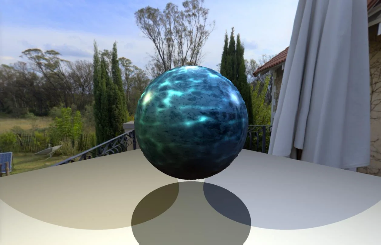 | 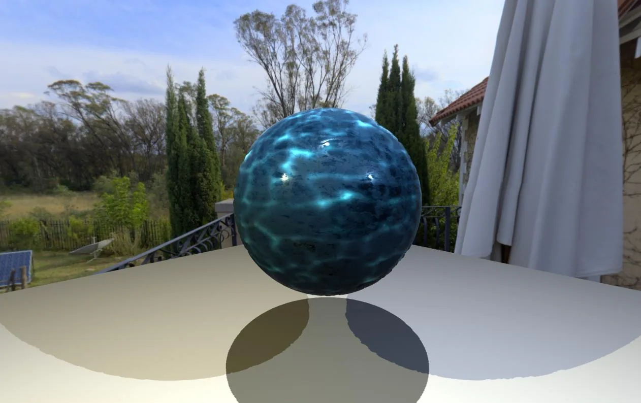 |
The thesis concluded that the specular reflections were "too diffuse, even at the lowest roughness", and that the colours of the individual lights stood out more than on the PBR sphere. Both follow from that one line. Blinn-Phong would have looked like this:
vec3 L = normalize(pointLights[l].position - vPos);
vec3 H = normalize(L + normalize(viewDir));
diffuseLight  += dotClamped(L, normal) * ...;
specularLight += pow(dotClamped(H, normal), exponent) * ...;
There's a second, smaller reason the highlights are soft. The exponent is smoothness * 100, a straight line from 0 to 100, but a glossy surface needs an exponent in the hundreds or thousands. The irony is that the shader already contains the right conversion and uses it only for reflections, which brings us to the next part.
Blurry reflections from mipmaps
Rough surfaces reflect blurrily. Doing that properly means integrating the environment over the specular lobe. Doing it cheaply means sampling a pre-blurred copy of the environment, and a mipmapped cube map already is a stack of pre-blurred copies, each level half the resolution of the one before. So the rougher the surface, the further down the mip chain the shader samples:
float GGXRoughnessToBlinnExponent(float roughness) {
  return 2.0 / pow(roughness, 2.0) - 2.0;
}

float getSpecularMIPLevel(float blinnShininessExponent) {
  float maxMIPLevelScalar = float(maxMipLevel);
  float desiredMIPLevel = maxMIPLevelScalar + 0.79248
                        - 0.5 * log2(pow(blinnShininessExponent, 2.0) + 1.0);
  return clamp(desiredMIPLevel, 0.0, maxMIPLevelScalar);
}
Roughness converts to an equivalent Blinn-Phong exponent (roughness 0.1 gives 198, roughness 0.5 gives 6). The exponent then picks the mip level whose texels are about as wide as the specular lobe. The magic number 0.79248 is log₂√3. And the same GGXRoughnessToBlinnExponent would also have given the point-light highlights above the right exponent.
I found one more twist only while porting the shader to this site. In WebGL 1, the third argument of textureCube is a bias, not an explicit level. So "sample mip 5" really meant "sample five levels blurrier than the hardware would have chosen". The result still reads as roughness, which is presumably why nobody noticed, me included.
The reflection vector is computed in view space and then brought back into world space so that it lines up with the cube map:
reflectVec = normalize((vec4(reflectVec, 0.0) * viewMatrix).xyz);
Two quiet details are packed into that line. w = 0 marks the vector as a direction, so the camera's position doesn't move it. And putting the vector on the left of the matrix multiplies by the transpose, which for a pure rotation is the inverse: view space back to world space, without a second uniform.
A gentle Fresnel term
Reflections get stronger at grazing angles. A road looks like a mirror near the horizon and like asphalt at your feet. The thesis shader handles this like so:
float fresnel = pow(dot(normalize(viewDir), normal) * 0.5 + 0.5, smoothness);
vec3 reflectionColor = getLightProbeIndirectRadiance(normal, roughness) * (1.0 - fresnel);
The * 0.5 + 0.5 remaps the cosine from [−1, 1] to [0, 1], so no edge case goes negative. Raising the result to smoothness, a number below 1, does two jobs at once. It shapes the falloff, and it scales the effect by roughness. As smoothness approaches 0, the power approaches 0 and anything to the power of 0 is 1, so 1 − fresnel goes to 0 and a fully rough surface reflects nothing. For the same reason, roughness is clamped to [0.001, 0.999] before any of this runs. Perfectly smooth and perfectly rough surfaces don't exist, and both extremes produce degenerate powers.
The industry-standard approximation is Schlick's: F0 + (1 − F0)(1 − N·V)⁵. Its fifth power holds steady at a base reflectance, about 4% for most non-metals, until close to the edge and then climbs steeply. The thesis noticed that 4% floor without naming it: on the PBR sphere, it wrote, the environment "lightly lights the whole object, whatever its roughness". Mine reflects nothing when viewed head-on and only brightens towards the rim.
Ambient occlusion: a strength slider that doesn't darken everything
The last map is ambient occlusion, the baked contact shadow in the crevices. It multiplies the final colour, and the viewer gives it a strength slider. The obvious implementation, ao * strength, is wrong: turn the strength down and the whole sphere goes dark. What you want is for strength 0 to mean no occlusion (multiply by 1) and strength 1 to mean the map as authored:
float ambientOcclusion = 1.0 - u_AOScale + u_AOScale * texture2D(u_AO, vUv).r;
That is mix(1.0, ao, strength) written out by hand. At low strengths only the darkest texels change noticeably, which is exactly how you want crevice darkening to fade in.
Then everything is added up and occluded:
vec3 finalColor = (diffuseColor + specularColor + reflectionColor) * ambientOcclusion;
Energy, approximately
A proper BRDF obeys two rules. The first is reciprocity: swap the light and the eye and you get the same answer. The second is energy conservation: a surface can't reflect more light than it receives. The thesis states plainly that it skips the second rule and uses two blunt stand-ins. The specular sum is multiplied by smoothness, so rough surfaces lose their highlight instead of gaining a wide bright one. The environment reflection is multiplied by ¾. Push the lights hard enough and the sphere will happily glow.
Why the viewer still runs the bug
When I ported the shader to this site, I fixed only what a modern Three.js refuses to compile. The half vector is still L, the shadows are still round and the mip "level" is still a bias. Colour management is switched off so that the maths runs on sRGB values exactly as it did in 2022. The viewer is an exhibit: it shows what the thesis defended, next to what it was measured against.
So open the Render Catalogue, pick Ice and flip Shading between Thesis shader and Three.js PBR. Then orbit the camera and watch which highlights move.